This post will cover how you can test a solar panel with a multimeter and how you can connect your solar panels in series and parallel.
Connecting to your Solar Panel
To test a solar panel with a multimeter, we must first determine which side is positive or negative.
In most cases, there will be a (+) and (-) label on the solar panel. Otherwise, there will often be a red and black wire, where the red wire will correspond to the positive lead, while the black wire will correspond to the negative lead.
*Note that there are other ways to connect as well such as through a JST connector or a DC Jack.
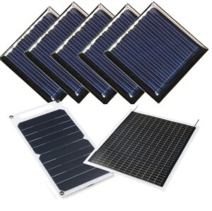
The solar panel pictured below is the Powerfilm 6V 50mA Flexible Solar Panel. It consists of lines shaped like an E. In this case, the two conductive strips on either side of the panel are the leads. The lead towards the spine of the E is the positive lead and the one on the opposite side is the negative lead.

Image from Crafting e-Fashion with DIY Electronics
To access the leads on these flexible solar panels, we must expose the conductive material by peeling the clear coating protecting the panels on either side. More hook-up methods for flexible solar panels can be found here.
Other panels like the Seeed Studio 0.5W rigid solar panel below contain colored wires where red is positive and black is negative. This panel has its output through a JST Connector. The back, which contains exposed conductive areas, will allow us to solder wires straight to it if needed, or if you like, you could cut off the JST connector and strip the wires.


Testing with a multimeter
To test your solar panels with a multimeter, begin by connecting the positive (+) and negative (-) sides of your solar panel to the corresponding probe on the multimeter: positive to red probe, negative to black probe. Note that the connection method will vary upon your chosen solar panel and hook-up method, but for testing, it may be beneficial to use something temporary like alligator clips, or conductive tape.
For panels with JST Connectors like this, you can use jumper wires. This provides you with exposed conductive material that you can clip alligator clips onto; making it easier to connect to your multimeter.

We want to set our multimeter at a value that exceeds our closest output for both voltage and current, but not by too much. So to test the voltage, set the multimeter dial to 20V and to test the current, set the multimeter dial to 200mA. Feel free to adjust this to the closest value higher than your expected output. If readings are coming out as 0, it might help to turn the dial down to increase sensitivity and if the multimeter reads OL or overloads, set the dial higher to decrease sensitivity. To learn more about the basics of using a multimeter, check out this tutorial from Sparkfun.
For this SEEED Studio 0.5W panel we are testing, we are expecting a maximum output of 5.5 Volts (V) at 100 milliamps (mA). This information can often be found on the seller’s site or on a provided datasheet. Note that reaching the maximum output is contingent upon the environment you are in. The indoor tests for this post were done on a rainy day with no sunlight and the outdoor tests were done at midday with full sunlight.


Indoor reading of single solar panel: 3.29 Volts (V), 73 microAmps (µA)


Outdoor reading of single solar panel: 6.34 Volts (V), 54 milliAmps (mA)
You can test your own panel in different environments: indoors, cloudy day, in direct sunlight, and more to get a better idea of how your panel will perform when in use. As you can see above, we get lower values than expected when we are testing the panel indoors but get exceedingly higher values when testing them outdoors.
Additionally, you can measure the voltage and current of panels connected in series or parallel.
Testing panels wired in series
Two identical panels wired in series should cause the voltage to double and cause the current to remain the same.
To wire your panels in series, connect the positive lead (+) of your first panel to the negative lead (-) of your second panel.
To test this circuit with a multimeter, close the circuit by taking the positive end of your second panel and connecting it to the red probe and by taking the negative end of your first panel and connecting it to the black probe of the multimeter.


Indoor reading of solar panels in series: 6.17 Volts (V), 69 microAmps (µA)


Outdoor reading of solar panels in series: 13.32 Volts (V), 48.9 milliAmps (mA)
As you can see, our voltage almost doubles from 3.29V to 6.17V indoors and from 6.34V to 13.32V outdoors. On the other hand, our current pretty much stays the same, only fluctuating a little in value.
Testing panels wired in parallel
Two identical panels wired in parallel should cause the current to double and cause the voltage to remain the same.
To wire your panels in parallel, connect the positive lead (+) of your first panel to the positive lead (+) of your second panel. Then do the same with the negative leads.
To test this circuit with a multimeter, close the circuit by taking the positive end of one of your panels and connecting it to the red probe of the multimeter and by taking the negative end of that same panel and connecting it to the black probe of the multimeter.


Indoor reading of solar panels in series: 3.00 Volts (V), 103 microAmps (µA)


Outdoor reading of solar panels in series: 6.43 Volts (V), 57.9 milliAmps (mA)
Here, you can see that our voltage pretty much remains the same while our current increases in value. Keep in mind that the angle of the solar panels relative to the sun matters. This could be the reason our current increases but does not necessarily double in value. Additionally, it could be because the panels were wired in parallel but no bypass diodes were used; this concept will be discussed further below.
Considerations
Apart from testing panels in different environments, it is worth testing how solar arrays or panels wired in parallel or series behave when there is a panel that is partially shaded.


You will notice a drastic loss in the output current. This often happens when wiring different solar panels together. In these situations, it is ideal to use Bypass and Blocking Diodes to prevent current from damaging partially shaded solar panels or flowing back into the solar panels and to allow you to efficiently utilize the power from your panels.
Bypass diodes are connected in parallel to the solar panels, allowing the current to have an alternative path to flow through when one solar panel is faulty or is shaded.
Blocking diodes are connected in series with the solar panels. This prevents a backflow of current onto shaded panels.
References:
Peppler, Kylie, et al. Soft Circuits : Crafting e-Fashion with DIY Electronics, MIT Press, 2014. ProQuest Ebook Central, https://ebookcentral-proquest-com.proxy.library.nyu.edu/lib/nyulibrary-ebooks/detail.action?docID=3339879.
PowerFilm List of Products (also has diagrams on series and parallel)