Light Coat

By IDM Grad Student Amy Hu 

A light sensing panel inside the lining of a jacket so that when jacket is opened, LEDs turn on to bring attention to the objects being displayed. 
A GIF shows jacket opening to display LEDs and a collection of pokemon pins

Materials
• 1 LilyPad
• 1 MicroUSB Cable
• 3 Adafruit LED Sequins
• 1 Photoresistor
• 1 10K Resistor
• 2 Coin Battery Holder
• 2 CR2032 Coin Battery
• Needle & Conductive Thread
• Fabric
• Alligator Clips
Set-Up
Before sewing material, test the circuit elements to make sure that they are working properly. Right click and open images in another tab to see them in a larger format.
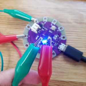
1. Use alligator clips to connect circuit elements between a breadboard to the LilyPad. Below is the circuit we would be testing, it uses a voltage divider to read the analog signal from the photoresistor.

On a LilyPad the analog pins have an “A” suffix and 5 digital pins. The power is the “+” and ground is “-“. 

2. Open the Arduino IDE and paste the following code into the window. Connect the LilyPad to your computer with the MicroUSB cable. Make sure under the “Tools” tab, the board is “LilyPad Arduino USB” and the port with the LilyPad is selected.

Connections
    Digital Pin 2 🡢 LED 
    Analog Pin 2 🡢 Photoresistor
    “thres” Variable 🡢 Adjust as needed, serial monitor will print these values.

Code
int
ledPin = 2;
int thres = 750;

void setup() {
  pinMode(ledPin, OUTPUT);
}

void loop() {
  Serial.println(analogRead(A2));
  if(analogRead(A2)>thres) {
    digitalWrite(ledPin, HIGH);
  } else
  {
    digitalWrite(ledPin, LOW);
  }
}

Light Off
Light On

Check that every LED works
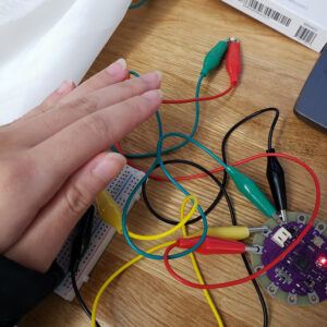
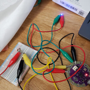
Prototype 1
This was my first attempt of making the system, where I made the system display Pokemon Gym Badges. 
Laying out the components. The voltage divider with the photoresistor and 10K resistor were placed on top relative to everything else.
The LED Sequins were connected in parallel to a digital pin. This set up was a messy one where things weren’t easy to lay out. Additionally, tying off knots were difficult in this stage because they would get loose.
First working test.

Lessons Learned: 
  • Using 2 Layers of Fabric made it possible to hide the traces on the under 
     section without it showing on the interface.
  • Better way to secure thread.
  • Lay everything being used out on fabric and use chalk or pencil to
    prototype where connections will go.
  • Analog Pins can be used to drive digital devices.

For Prototype 2:
  • Have different light patterns when displayed.   
  • Make lights run independently of each other.
  • Power the device with coin cell batteries.

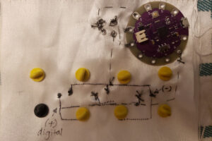
Prototype 2
Using what I learned in my previous prototype I made a different iteration that would be run using coin cell batteries.
  
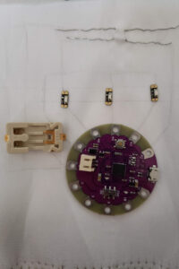
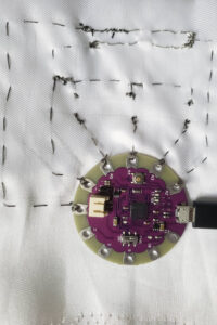
The above traces are first made with pencil and then filled in with conductive thread. With this layout, it’s a lot easier to see where parts are connected with one another. For the legs of the photoresistor and resistor, there is normal thread used to hold them more securely.
 
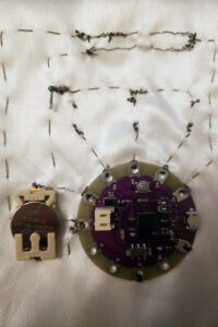
The cell holder is connected to the “+” and “-” terminals of the LilyPad which will power the system. There is a 3.7V power requirement from the LilyPad so another coin cell battery was added in series. Note:  Delay Function
The “Blink” Example in the Arduino IDE calls delay() which pauses the program. With the program paused, it can cause any sensor reading for values in the loop function to be missed or skipped.Instead we’re using this work around:
  LEDms = millis();
  LEDdelay = 500;
 
  if(LEDms - LEDprev > LEDdelay) { //check if delay passed
    LEDprev = LEDms;
With this code every half a second, it will check if the delay has passed. If so, we’d change the previous time to be the current time and write what we want to change in the if statement. For our case, we would be checking if the photoresistor is covered or not at a given time.
Code
int photor = A2, led1 = A3, led2 = A4, led3 = A5;
int thres = 600;
int ms, LEDms, LEDprev, LEDdelay;
int LEDstate = LOW;
int LEDcount = 0;
boolean cover = true;

void setup() {
  pinMode(led1, OUTPUT);
  pinMode(led2, OUTPUT);
  pinMode(led3, OUTPUT);
}

void loop() {
  //photoresistor is covered
  if(cover == true) {
    digitalWrite(led1, LOW);
    digitalWrite(led2, LOW);
    digitalWrite(led3, LOW);
   
    if(analogRead(photor)>thres) {
      cover = false;
      ms = millis();
    }
  }

  //photoresistor is not covered
  else {
    switch(ms%4) {
      case 1:
        blinkZoom();
      break;
      case 2:
        blinkBacknForth();
      break;
      case 3:
        blinkEveryOther();
      break;
      default:
        blinkAll();
      break;
    }
    if(analogRead(photor)<thres) {
      cover = true;
    }
  }
 
}

/*
* blinkAll()
* Checks if amount of time have passed and if so will turn all LEDs on or off.
*/
void blinkAll() {
  LEDms = millis();
  LEDdelay = 500;
 
  if(LEDms - LEDprev > LEDdelay) { //check if delay passed
    LEDprev = LEDms;
    if(LEDstate == LOW)
      LEDstate = HIGH;
    else
      LEDstate = LOW;
    digitalWrite(led1, LEDstate);
    digitalWrite(led2, LEDstate);
    digitalWrite(led3, LEDstate);
  }
}

/*
* blinkEveryOther()
* Checks if amount of time have passed and if so will blink every other LED.
*/
void blinkEveryOther() {
  LEDms = millis();
  LEDdelay = 250;
  if(LEDms - LEDprev > LEDdelay){
    LEDprev = LEDms;
    if(LEDstate == LOW) {
      digitalWrite(led1, LOW);
      digitalWrite(led2, HIGH);
      digitalWrite(led3, LOW);
      LEDstate = HIGH;
    }
    else {
      digitalWrite(led1, HIGH);
      digitalWrite(led2, LOW);
      digitalWrite(led3, HIGH);
      LEDstate = LOW;
    }
  }
}

/*
* blinkBacknForth()
* Checks if amount of time have passed and if so will blink LED back and forth.
*/
void blinkBacknForth() {
  LEDms = millis();
  LEDdelay = 250;
  if(LEDms - LEDprev > LEDdelay) {
    LEDprev = LEDms;
    LEDcount++;
  }
  switch(LEDcount%4) {
    case 1:
      digitalWrite(led1, LOW);
      digitalWrite(led2, HIGH);
      digitalWrite(led3, LOW);
    break;
    case 2:
      digitalWrite(led1, LOW);
      digitalWrite(led2, LOW);
      digitalWrite(led3, HIGH);
    break;
    case 3:
      digitalWrite(led1, LOW);
      digitalWrite(led2, HIGH);
      digitalWrite(led3, LOW);
    break;
    default:
      digitalWrite(led1, HIGH);
      digitalWrite(led2, LOW);
      digitalWrite(led3, LOW);
    break;
  }
}

/*
* blinkZoom()
* Checks if amount of time have passed and if so will blink LED from left to right.
*/
void blinkZoom() {
  LEDms = millis();
  LEDdelay = 150;
  if(LEDms - LEDprev > LEDdelay) {
    LEDprev = LEDms;
    LEDcount++;
  }
  switch(LEDcount%3) {
    case 1:
      digitalWrite(led1, LOW);
      digitalWrite(led2, HIGH);
      digitalWrite(led3, LOW);
    break;
    case 2:
      digitalWrite(led1, LOW);
      digitalWrite(led2, LOW);
      digitalWrite(led3, HIGH);
    break;
    default:
      digitalWrite(led1, HIGH);
      digitalWrite(led2, LOW);
      digitalWrite(led3, LOW);
    break;
  }
}
Demo
Blink
Zoom
Back & Forth
Every Other
css.php