Level: Intermediate-Advanced
The goal of this project was to use flexible, conductive materials (eTextiles) in combination with flexible solar panels to create a garment that can reliably generate power while also being durable, flexible and comfortable, ie– wearable!
This tutorial uses one speciality tool: a Grommet Press, available in the IDM proto lab. However, there are other hook-up options available if you do not have access to a press.
This project could be modified to be more or less complex, we recommend you skim through the whole thing, then spend time in the ideation phase to come up with a design that works for you. Email us at kmm464 AT nyu DOT edu if you have an iteration you’d like to share!
Contents
- Supplies
- Ideate and Project Plan
- Plan Hook-Up Methods
- Prepare Fabric
- Conductive Nylon Tape Traces
- Attach Panels to Traces
- Construct Light Messages (optional)
- Blinking Circuit (optional)
- Light Messages Trace Layer (optional)
- Sewing Ring Connectors
- Insulate
- Sew and Turn Fabric
- Final Thoughts
Supplies
Scarf:
- Flexible Solar Panels (can also be purchased at Digikey or Amazon)
- Conductive Fabric Tape
- Romed conductive fasteners, or another hook-up method, (see step 3)
- Fabric for scarf (about 1 yard at least 60” wide)
- Ribbon for window trim (optional)
- Hook-up Wire
- Conductive Thread
- Solar Lipo Charger (We used this one from Seed studio but variations exist, ex. Sparkfun, Adafruit)
- Rechargeable 3.7 Lipo battery
- Ring Crimp Connectors, example
Blinking Circuit (if using):
- White LEDs
- Flexible PCB
- 2 x npn transistors (I used 2N3904)
- 2 x 10 uf capacitors
- 2 x 100 k resistors
- 2 x 470 ohm resistors
- Soldering Iron
Ideate and Project Plan
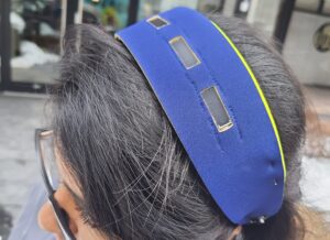
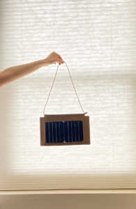
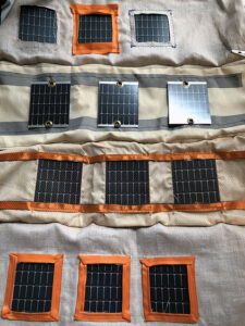
These images show some of our initial tests with hooking up solar panels to conductive fabric ribbon (more details in step 2). You can see we were trying to get a sense of how we wanted our panels to look in the garment, thinking about an oversized scarf or maybe a tunic, as well as thinking about how we wanted to use the accent color.
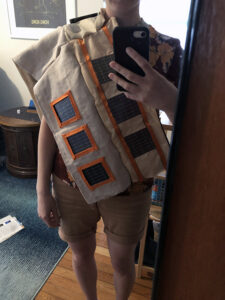

Ultimately we settled on a scarf design with windows and mismatched accent trim, with the solar panels charging a battery, to power LED messages. We thought the mismatched trim created a more interesting pattern than framing all the windows the same way, and would accent the LED messages well when they appear.
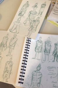
When you’ve settled on a design, make sure you think through all the elements of how it will come together before you start. Here is a drawing we made as we thought through the process of construction, and a more polished diagram by former grad student Bo, that should be easier to follow.


The construction workflow for the scarf is:
- Line a piece of fabric with conductive tape. This will be trace layer (B)
- Attach solar panels to layer B. (measure first, to get your placement where you want it)
- Align layer A on top of layer B. Trace or measure solar panel locations to cut windows.
- Stack Layer A on top of Layer B and sew or around edges, leaving one short side open.
- Another piece of fabric, Layer C, will be the bottom layer. Stack it on top of layer A, (windows) and sew around 3 sides. Then turn inside out. This will result in a sandwich: Bottom Layer. (c), Inner Layer (b) with panels, Top Layer (a), and it will hide our stitches and our traces.
We ended up adding a second inner trace layer (B2), for the LED messages, which is optional, and depends on what you want to power. More details on this are in step 8.
3. Plan Hook-up Methods
There are many different ways you can decide to run power from your solar panels to your desired output. The flexible panels we identified here are a little trickier than standard panels because of the waterproof coating. As such, we tested several different ways to connect them, and made an entire post about it. Have a look at what supplies you have and do a test before you start.
For the Solar Scarf, we used Step 4, and used a press to attach solar panels directly to a piece of fabric with conductive nylon tape on it.
Planning your hook-up method should help you choose your trace materials (ie, wire, ribbon), and also solidify your design. Do you need windows? Or will you mount your panels to the front of your scarf and cover traces with ribbon?
4. Prepare Fabric
This scarf requires 3-4 pieces of fabric, 60” long, and 8-10” wide. I prefer a wider look for this scarf. We cut our fabric 10”, to leave plenty of room for sewing seams.
Whether you need 3 or 4 pieces depends on whether you need 1 or 2 trace layers (step 8-9). We used 2 trace layers, and 2 outer layers, so 4 pieces of fabric total.

On the top piece, we cut windows, so the solar panels would be visible through them, but the silver traces would be covered. We used a light-weight linen fabric that frays, so we had to fold the edges of the windows and sew them to stop the fraying. In some places, we trimmed the windows with ribbon. It would have been much easier to use a fabric that doesn’t fray, like felt or neoprene.
We measured the size of our panels and the distance we wanted between them, before we cut our windows. Later, we use the window layer as a guide to place our solar panels on the trace layer when it came time to attach them (Step 6).
I recommend cutting one window at a time, and checking the size against the solar panel as you go. If you need to sew or trim your window edges, you should cut them smaller than you think you need, so you have extra fabric to fold back. Laying out the windows was probably the most labor intensive step for us. (Again, a non-fraying fabric would help). Sorry that I don’t have step by step photos for this step, but here are some photos from the different tests.


5. Conductive Nylon Tape Traces
For this project, I used conductive nylon fabric tape from Adafruit. This tape has a pretty strong adhesive on the back so in theory, you could simply press it onto your fabric directly. For added security, I decided to also sew the ribbon down with a sewing machine, using conductive thread in the bobbin. Another option is to use iron-on interfacing.

Before you lay-out your traces on your fabric, measure the size of your panels and make sure they will make contact with the traces on either edge.*

You also should have a sense of your power requirements for your project, and make a plan for how you want to wire them (series, parallel, or a combination). These flexible panels are described as being capable of 50mA at 4.8V, though I’ve measured them outputting up to 6.5V. My “LiPo Rider Pro,” which will allow me to charge a lipo battery from the solar panels has the following description:

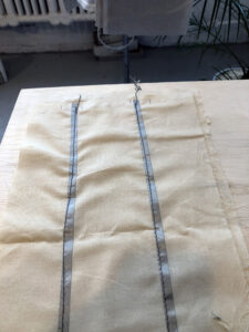
By connecting 8 Solar panels in parallel, I can keep my voltage the same (as I do not want to exceed 6.5V), and increase the current from 50mA in a single cell, up to 400mA. A parallel circuit is also a perfect layout for the scarf configuration, as it just requires two parallel lines running down the fabric, like a train track. I did not use bypass diodes in this project because it won’t be used without a human present, but for autonomous projects, it is worth considering.
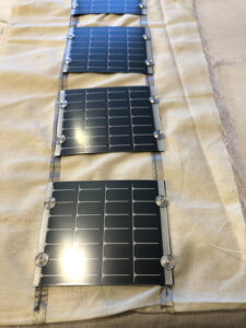
6. Attach panels to traces
As mentioned earlier, I ended up using specialty fasteners from Romed and purchased a die press to go with it. I attached the panels directly to the conductive nylon tape trace layer. Another option would’ve been to make them removable, by attaching the socket to the panels, and the snap end to the fabric. You can see the whole process in step 4 of this post.

Alternatively, you could use a hand punch to install grommets from a craft or hardware store, but make sure they are conductive!
7. Construct Light Messages
I constructed the messages using individual LEDs in a flexible protoboard. All of the LEDs are connected in parallel (positive to positive, negative to negative). On the back of the PCB, I bent the LED legs to connect them to each other and added solder. In most cases, the legs were long enough to make the connections, but in a few places, extra jumper wire was necessary.
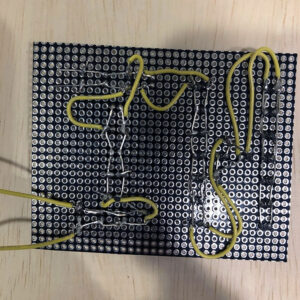
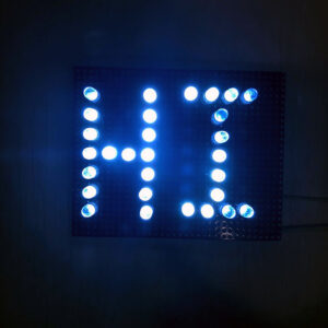
I had done variations of this method before, and I enjoy it, but it takes a few hours. I draw the design on paper first, and think about how I am going to bridge all the connections. It’s very important not to mix up power and ground, pay attention to the flat side of your led (ground).

I usually test as I go to avoid errors, using a 3.3V (coin cell) battery. I add long jumper wires to my first LED (bottom of the “I” in images above) to make testing easier. When I’m done, I’ll use the jumpers to connect the LED message to the solar circuit in the scarf. Fabric will help diffuse the LEDs.

8. Blinking Circuit
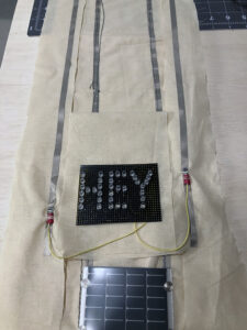
Once my LED messages were complete, I connect the power and ground wires to a breadboard to test my blinking circuit, and then moved the circuit over to a pcb, which I connected to my solar charging shield.

There are many ways to make an LED blink, a 555 timer is a common way, and of course you can use a microcontroller, but that will also increase your power draw. I wanted to keep things simple so I used an “astable multivibrator,” an oscillator circuit that uses two transistors, two capacitors, and two loads (LEDs in this case) to pass power back and forth, so the LED signs alternate when they are on an off.
Here’s a really nice explanation of how the circuit works: https://www.build-electronic-circuits.com/astable-multivibrator/
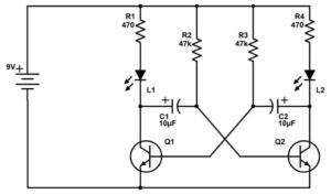
As the author writes, think of the transistor as a switch. If you are new to transistors, and especially if you are swapping out the npn transistor for a different variety (I used 2N3904), make sure you check the data sheet to identify which leg is base, collector, or emitter. This will impact your wiring.
Changing the values of the capacitors and resistors will change the rate of the blinking, which is why it is important to test on a breadboard. Once you’re happy with your circuit, take detailed notes so you can move it over to a pcb without making any mistakes. I find that drawing the circuit helps me commit it to memory.


My blinking circuit is getting power from the Solar Rider circuit (the blue PCB), via a stripped USB connector. The blinking circuit needs to deliver power to the LED messages via the trace layer (next step). I used a piece of foam to keep all the elements of my final circuit stable.
9. Trace Layer for LED Messages
As mentioned in the planning phase, I decided to power the LED messages from a battery, which is being charged by the solar panels. This way, the LEDs will work when I am inside. If I tried to power them directly by the solar panels, they would only be on in bright sunlight, where they would be hard to see.
If you have a design that only requires direct power, OR if your load is attached to the end of the scarf, (as opposed to halfway through the scarf, the way my messages are) this step may not be relevant to you. I needed to run power through the scarf to the LED message “HEY”, so an additional trace layer was necessary.
Just like the solar trace layer, this layer consists of a piece of fabric with conductive nylon tape on either side to run power and ground. To isolate it from the solar trace layer below it, and to prevent the fabric from covering the solar panels, I made this trace layer wider, and cut out the middle section. I connected the blinking circuit and the LED signs to the trace layer using sewable ring connectors (Next step)


10. Sewing Ring Connectors
To bring it all together, the connections I needed to make were:
- Solar panel fabric traces to solar charging circuit
- Charging circuit to blinking circuit
- Blinking circuit to LED trace layer
- LED messages to LED trace layer
I did not need to sew the connection between the solar charging circuit and the blinking circuit (2), because they were both on pcbs, I used a usb connector with one end stripped to connect to the blinking circuit pcb. (Step 8).
Connecting the solar fabric traces to the solar charging circuit is a case of needing a hard-to-soft connection, a common problem in wearables. The INPUT to my solar charging circuit is a JST connector. I soldered long wires to the end of the JST connector, and then used the crimp tool on my wire stripper to attach a ring connector to each wire. I then sewed the ring connectors directly to my traces, using conductive thread. There is one on the positive side and one on the negative side. The ring connector is not strictly necessary, you could also strip the wire and sew the copper to the trace directly. However, you can not solder the wire to the fabric trace, it will melt.


The blinking circuit also has a power and ground which I attached to the blinking circuit traces using the same method. I also had to hook the LED signs up to the traces so they could access the power.


11. Insulate
Before turning your fabric right side out it is very important to insulate all exposed elements. This is a flexible piece and you want to avoid an accidental short, that could be caused by two exposed elements touching.
The conductive thread connections we made in the previous step pass through the back of the fabric, and so need to be insulated on the back. You can do this with nail polish, tape, or by sewing non-conductive thread over the top.

I also insulated the back of my grommets with nail polish. The trace layers will be insulated by the top fabric piece.


12. Sew and Turn Fabric
The final step is to sew the top fabric piece on, as you can see from this image, which shows the construction order.
A small dab of super glue, hot glue, or fabric glue in corners of windows can help ensure they stay aligned to the solar panels when sewing.
It’s a little hard to turn the garment inside out because it’s so long, but by proceeding carefully, it worked and we were left with a final piece with nicely hidden seams. I added velcro to the final edge so I can access the electronics, and take things out for washing.


As a final step, we sewed a mask out of matching fabric following this pattern. If you’re new to sewing, masks patterns are a great starter project to get comfortable.

^I also added arm straps to the back of the scarf but they weren’t really necessary.
13. Final Thoughts
Making the scarf is not a trivial task, it actually took quite a bit of testing and planning. But even if you don’t follow the process we set-out exactly, we hope it can inform your own project planning and direction, as you approach your own solar-powered wearable. Good luck!